Standby Mode
Materials
AMB82-mini x 1
Optional: Push button x 1
Optional: Register 220 ohms x 1
Optional: USB to ttl serial cable x 1
Example
In this example, the development board will demo the non retention Standby Mode for power save. There are 6 wake-up sources. The system will count down 5s then go to Stand By mode. Upon the wake-up source being triggered, the system will be reboot and wake up again.
The module and board power consumption report under Standby mode are listed in these two tables below.
RTL8735B module power consumption test results
Wake-up source |
Module power consumption (uA) |
|---|---|
Stand By Mode (measure at 3V3) |
|
AON timer |
41.22 |
AON GPIO |
41.28 |
RTC |
41.46 |
PON GPIO |
41.07 |
UART/Serial1 |
41.32 |
Gtimer0 |
41.48 |
AMB82-MINI board Power Consumption
Wake-up source |
Development board power consumption Approximate measurement (mA) Voltage source : V_USB(5V) |
Development board power consumption Approximate measurement (mA) Voltage source : V_USB(3V) |
Development board power consumption Approximate measurement (mA) Voltage source : USB CH340(MicroUSB) |
Development board power consumption Approximate measurement (mA) Voltage source : USB OTG |
||||
|---|---|---|---|---|---|---|---|---|
Normal Mode |
Standby Mode |
Normal Mode |
Standby Mode |
Normal Mode |
Standby Mode |
Normal Mode |
Standby Mode |
|
AON timer |
57.56 |
3.46 |
83.81 |
5.26 |
60.32 |
5.67 |
57.56 |
3.46 |
AON GPIO |
57.56 |
3.46 |
83.81 |
5.26 |
60.32 |
5.67 |
57.56 |
3.46 |
RTC |
57.56 |
3.46 |
83.81 |
5.26 |
60.32 |
5.67 |
57.56 |
3.46 |
PON GPIO |
57.56 |
3.46 |
83.81 |
5.26 |
60.32 |
5.67 |
57.56 |
3.46 |
UART/Serial1 |
57.56 |
3.46 |
83.81 |
5.26 |
60.32 |
5.67 |
57.56 |
3.46 |
Gtimer0 |
57.56 |
3.46 |
83.81 |
5.26 |
60.32 |
5.67 |
57.56 |
3.46 |
Note
The USB‑UART bridge (CH340) and indicator LEDs (D1, D2, D3 with resistors R85, R101) were originally included to provide a better user experience. However, to achieve improved power consumption results, we eliminated these non‑essential current paths so that the measured values reflect only the SoC and essential circuitry.
Wake-up source |
Development board power consumption Approximate measurement after removing CH340 and LEDs (mA) Voltage source : V_USB(5V) |
Development board power consumption Approximate measurement after removing CH340 and LEDs (mA) Voltage source : V_USB(3V) |
Development board power consumption Approximate measurement after removing CH340 and LEDs (mA) Voltage source : USB CH340(MicroUSB) |
Development board power consumption Approximate measurement after removing CH340 and LEDs (mA) Voltage source : USB OTG |
||||
|---|---|---|---|---|---|---|---|---|
Normal Mode |
Standby Mode |
Normal Mode |
Standby Mode |
Normal Mode |
Standby Mode |
Normal Mode |
Standby Mode |
|
AON timer |
54 |
0.28 |
81 |
1 |
54 |
0.2 |
54 |
0.2 |
AON GPIO |
54 |
0.28 |
81 |
1 |
54 |
0.2 |
54 |
0.2 |
RTC |
54 |
0.28 |
81 |
1 |
54 |
0.2 |
54 |
0.2 |
PON GPIO |
54 |
0.28 |
81 |
1 |
54 |
0.2 |
54 |
0.2 |
UART/Serial1 |
54 |
0.28 |
81 |
1 |
54 |
0.2 |
54 |
0.2 |
Gtimer0 |
54 |
0.28 |
81 |
1 |
54 |
0.2 |
54 |
0.2 |
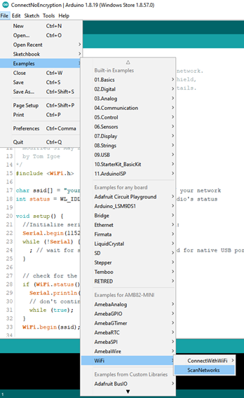
Open example in File -> Examples -> AmebaPowerMode -> StandbyMode
Next is setting up the system and entering the power mode. Please refer to the following steps for entering Standby mode.
Use the USE_MULTIPLE_WAKEUP_SOURCES configuration flag to set for multiple or single wakeup sources.
Multiple Wake-up Sources
You can use bitwise OR to setup multiple wakeup sources for MULTI_WAKEUP_SOURCE
SLP_AON_TIMER (BIT0) - AON Timer wakeupSLP_AON_GPIO (BIT1) - AON GPIO wakeupSLP_RTC (BIT2) - RTC wakeupSLP_PON_GPIO (BIT4) - PON GPIO wakeupSLP_UART (BIT6) - UART wakeupSLP_GTIMER (BIT7) - GTimer wakeupFor AON timer, please set CLOCK value to 0 or 1, 0:100kHz, 1:4MHz, SLEEP_DURATION unit is in seconds.
For AON GPIO, please set the AON_GPIO_PIN value to 21 or 22.
For RTC, please set the value for ALARM_DAY, ALARM_HOUR, ALARM_MIN, or ALARM_SEC. All alarm values set the duration of RTC wake-up. The range is “1day, 0h, 0m, 0s” to “365day, 23h, 59min, 59s”.
For PON GPIO, please set the PON_GPIO_PIN to value between 0 and 11. The GPIO pin is set to active high, please refer to the following connection.
For UART/Serial1, there is no setting required. However, USB to ttl serial cable Tx(green) and Rx(white) pin needs to connect to Serial1 Rx and Tx pin. Refer to the following connection. (Power 5V/3.3V Red, Ground Black)

For GTimer, please set the value for GTIMER_DURATION, the timer sleep duration in seconds.
Single Wake-up Sources
For UART/Serial1, there is no setting required. However, USB to ttl serial cable Tx(green) and Rx(white) pin needs to connect to Serial1 Rx and Tx pin. Refer to the following connection. (Power 5V/3.3V Red, Ground Black)