MPU6050 IMU Zero
Materials
AMB82-mini x 1
MPU6050 x 1
Example
Introduction
This example will demonstrate how to do calibration for the MPU6050 IMU.
Procedure
Connect the MPU6050 to I2C_SDA and I2C_SCL of the board as shown in the diagram below.
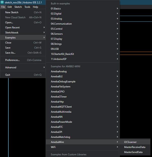
Open the example in “File” -> “Examples” -> “AmebaWire” -> “MPU6050”-> “MPU6050_IMU_Zero”
then it will report 0 for all accelerations and displacements, except for Z acceleration, for which it will report 16384 (that is, 214). Your device probably won’t do quite this well, but good offsets will all get the baseline outputs close to these target values. Put the MPU6050 on a flat and horizontal surface and leave it operating for 5-10 minutes so its temperature gets stabilized.
The line just above the “done” line will look something like [567,567] –> [-1,2] [-2223,-2223] –> [0,1] [1131,1132] –> [16374,16404] [155,156] –> [-1,1] [-25,-24] –> [0,3] [5,6] –> [0,4].
As will have been shown in interspersed header lines, the six groups making up this line describe the optimum offsets for the X acceleration, Y acceleration, Z acceleration, X gyro, Y gyro, and Z gyro, respectively. In the sample shown just above, the trial showed that +567 was the best offset for the X acceleration, -2223 was best for Y acceleration, and so on.
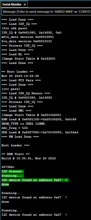
Below shows the Serial Monitor output for running this example.


