NAU7802 Advanced I2C
Materials
Example
Introduction
This example shows how to configure a different I2C bus with different clock speed for NAU7802.
Procedure
Connect the Load Cell to NAU7802.
Connect the red wire of Load Cell to RED pin (Excitation +) of NAU7802.
Connect the black wire of Load Cell to BLK pin (Excitation -) of NAU7802.
Connect the green wire of Load Cell to GRN pin (Signal +) of NAU7802.
Connect the white wire of Load Cell to WHT pin (Signal -) of NAU7802.
Connect the AMB82-mini to NAU7802.
Connect the VDD33 of AMB82-mini to 3V3 of NAU7802.
Connect the GND of AMB82-mini to GND of NAU7802.
Connect the Pin 09 (I2C_SDA1 pin) of AMB82-mini to SDA of NAU7802.
Connect the Pin 10 (I2C_SCL1 pin) of AMB82-mini to SCL of NAU7802.
Note
Download User Guide to understand more on pin definition. If you are following through all other NAU7802 examples for AMB82-mini, do remember to configure your I2C pins properly, this example uses Pin 09 and Pin 10.
Tip
Depending on your NAU7802 version, some may support 5V+ operating voltage—please check the official website before you connect to a 5V power supply. If your NAU7802 supports 5V+ operating voltage, connecting to V_USB instead of VDD33 tends to have less jitter effect.
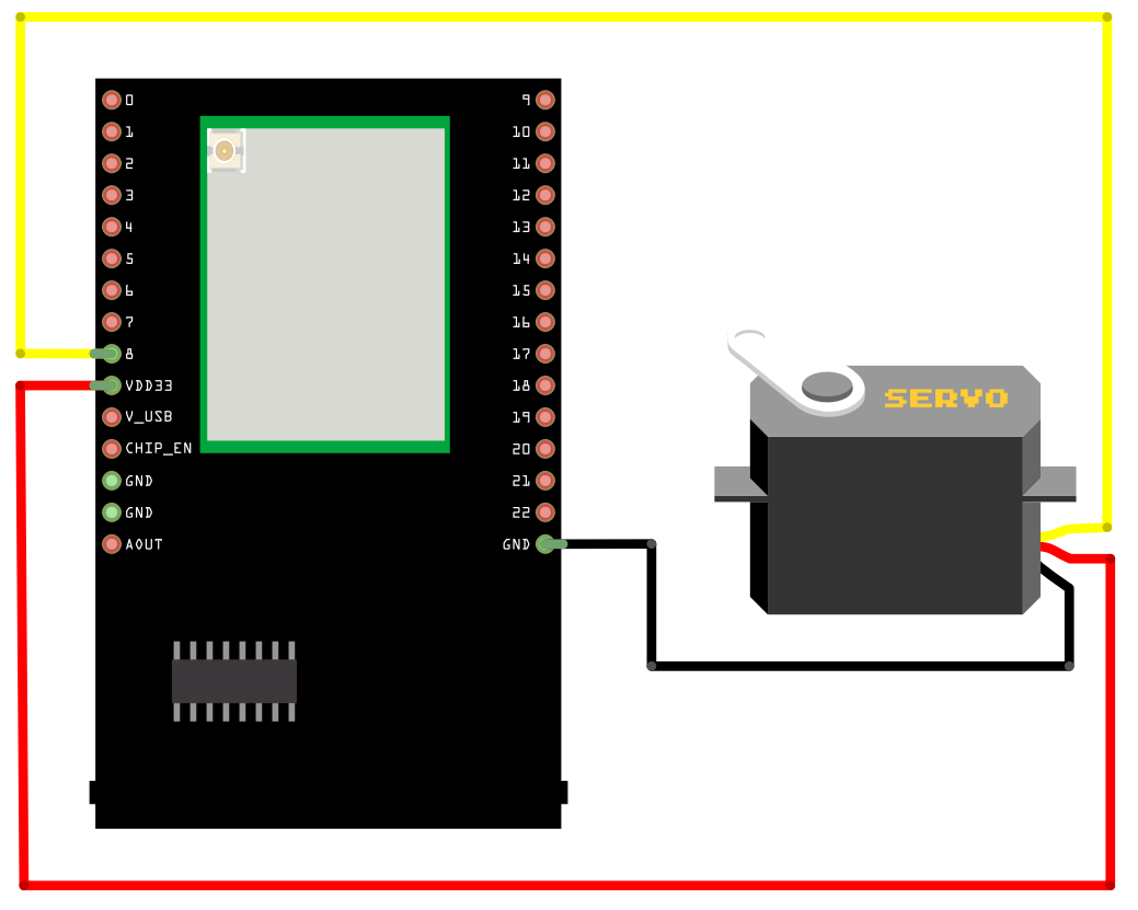
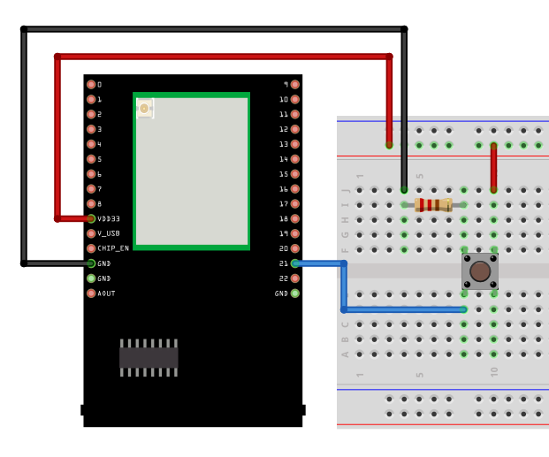
The final wiring should look like the diagram below.
Open the example in File -> Examples -> AmebaWire -> NAU7802 -> AdvancedI2C
Compile and run the example.
The NAU7802 supports up to 400k Hz. You can also pass different wire port into the library.