NAU7802 Interrupt
Materials
Example
Introduction
This example shows how to use SparkFun NAU7802 to get raw readings from a Load Cell via interrupt mechanism.
Procedure
Connect the Load Cell to NAU7802.
Connect the red wire of Load Cell to RED pin (Excitation +) of NAU7802.
Connect the black wire of Load Cell to BLK pin (Excitation -) of NAU7802.
Connect the green wire of Load Cell to GRN pin (Signal +) of NAU7802.
Connect the white wire of Load Cell to WHT pin (Signal -) of NAU7802.
Connect the AMB82-mini to NAU7802.
Connect the VDD33 of AMB82-mini to 3V3 of NAU7802.
Connect the GND of AMB82-mini to GND of NAU7802.
Connect the Pin 12 (I2C_SDA pin) of AMB82-mini to SDA of NAU7802.
Connect the Pin 13 (I2C_SCL pin) of AMB82-mini to SCL of NAU7802.
Connect the Pin 2 (GPIO pin) of AMB82-mini to INT of NAU7802.
Note
Download User Guide to understand more on pin definition.
Tip
Depending on your NAU7802 version, some may support 5V+ operating voltage—please check the official website before you connect to a 5V power supply. If your NAU7802 supports 5V+ operating voltage, connecting to V_USB instead of VDD33 tends to have less jitter effect.
The final wiring should look like the diagram below.
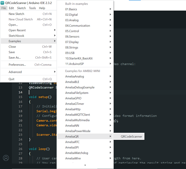
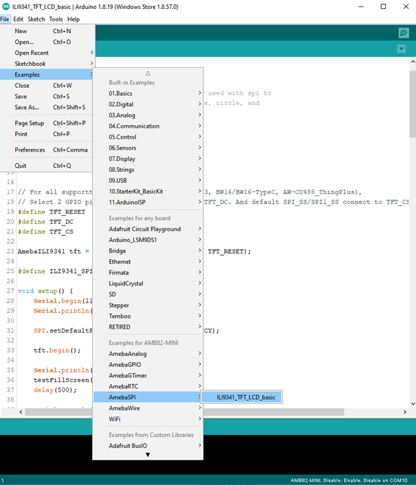
Open the example in File -> Examples -> AmebaWire -> NAU7802 -> Interrupt
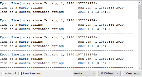
Compile and run the example.
The INT (interrupt) pin on the NAU7802 indicates when a sample has been taken, which is different from the NAU7802 Basic Reading example, where a polling mechanism is used. This example shows how the INT pin can be configured as active high or active low.