Dual Board I2C Master
Materials
AMB82-mini x 2
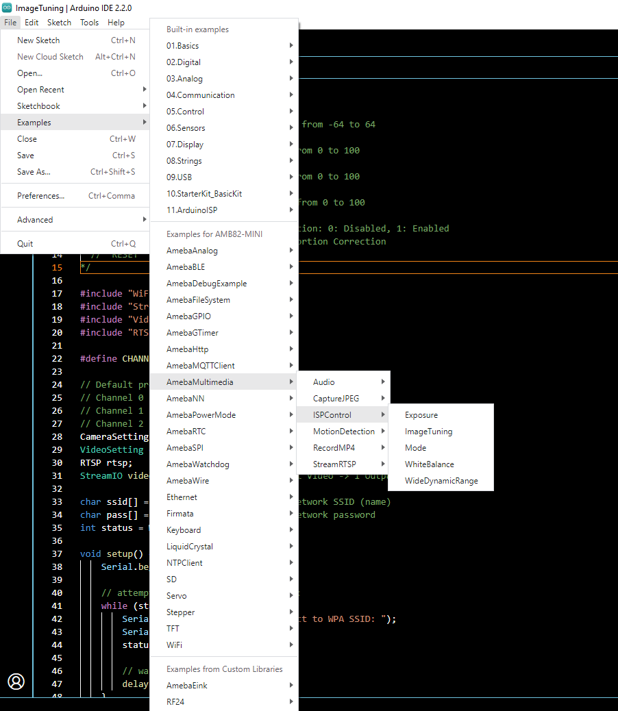
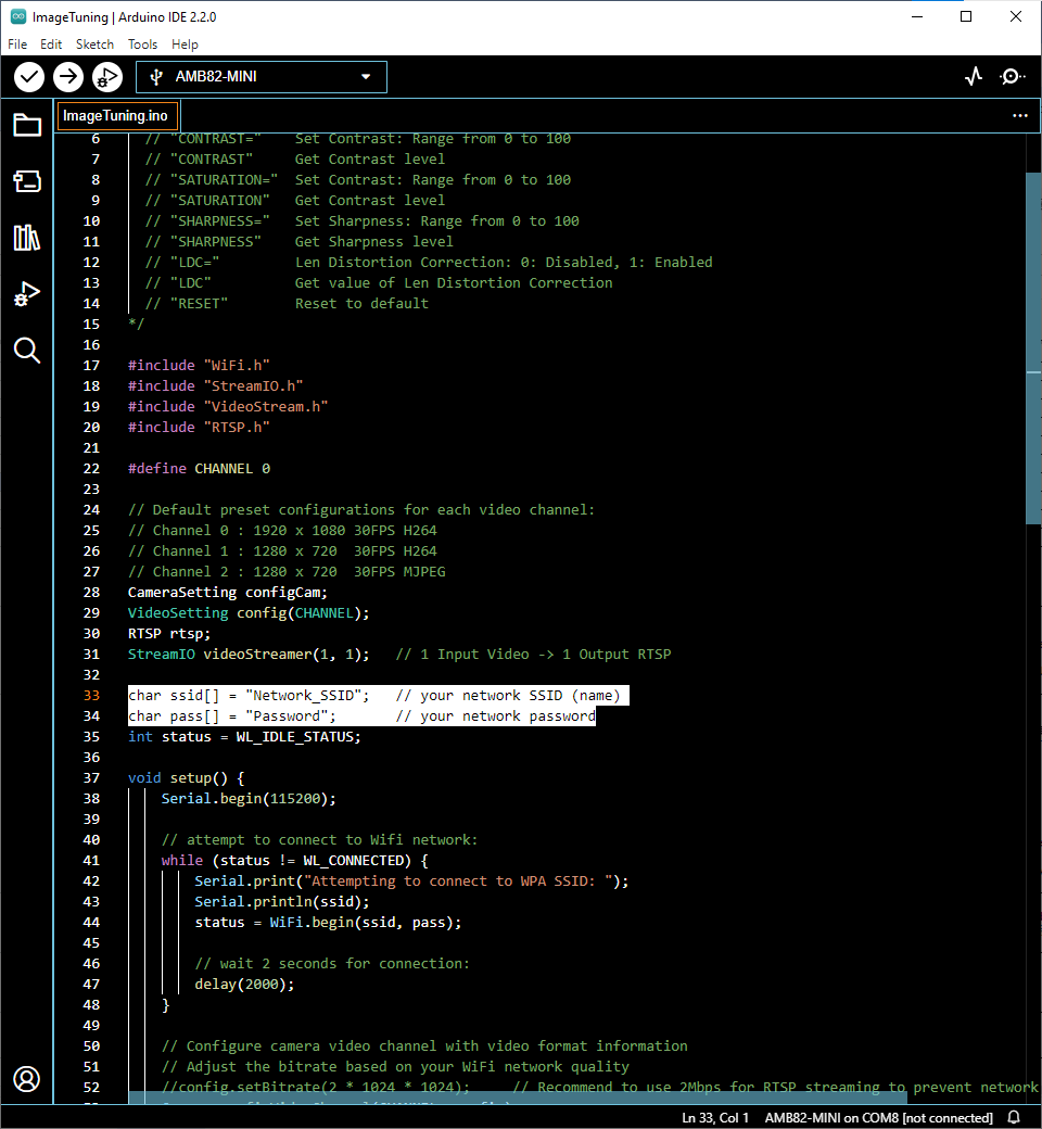
Example
I2C Introduction
There are two roles in the operation of I2C, one is “master”, the other is “slave”. Only one master is allowed and can be connected to many slaves. Each slave has its unique address, which is used in the communication between master and the slave. I2C uses two pins, one is for data transmission (SDA), the other is for the clock (SCL). Master uses the SCL to inform slave of the upcoming data transmission, and the data is transmitted through SDA. The I2C example was named “Wire” in the Arduino example.
Introduction
In this example, two AMB82-mini boards communicate with each other over I2C. One board is configured as the I2C master and the other as the I2C slave at address 0x08. The master first sends 127 bytes of data (0x02 to 0x80) to the slave at 100 kHz, then requests 127 bytes in return. The master verifies that the received data matches the expected values (0x01 to 0x7F) and prints the verification result to the Serial Monitor.
This example uses the I2CMaster_dual sketch on the master board, paired
with the I2CSlave_dual sketch on the slave board.
Procedure
Setting up the Slave Board
Click Sketch -> Upload to compile and upload the example to the slave AMB82-mini.
Setting up the Master Board
Click Sketch -> Upload to compile and upload the example to the master AMB82-mini.
Wiring
Code Reference
Wire.begin() to join the I2C bus as a master.Wire.setClock() to set the I2C clock frequency.Wire.beginTransmission(address) to begin a transmission to the I2C slave with the given address.Wire.write() to queue bytes for transmission from master to slave.Wire.endTransmission() to end a transmission to a slave and transmit the queued bytes.Wire.requestFrom(address, quantity) to request bytes from a slave device. Retrieve the bytes using Wire.available() and Wire.read().